Skunned Knuckles
Skunned Knuckles Articles
by Orest Lazarowich
Four Wheel Drive Suspension And Steering
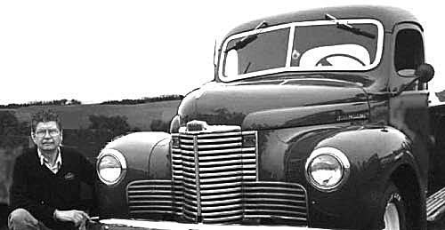
“Rides like a lumber wagon.” I am sure you have heard that phrase, and maybe you have used it yourself. A lumber wagon is a loading platform set on two axles without any type of suspension. If you own a military Jeep, or a Jeep CJ- 2A, CJ-3A or CJ-3B, you may believe that you are riding in a lumber wagon. There is very little comfort in these vehicles. They are built on an 80 inch wheelbase which compresses the driving compartment and makes long distance driving uncomfortable. The seat cushions have very little padding, and there is no seat adjustment. The short wheelbase and stiff suspension result in a choppy ride. The rear bench seat is a real ‘pile driver’ because it sits over the rear axle. Many war photographs show the Generals riding in the front passenger seat. Did you ever wonder why?The high center of gravity can cause a problem in corners, if the speed is excessive. There is very little protection in bad weather. Still, these are great vehicles for regular off-roading and short distance travel. The ride quality on what is called the compact style SUV didn't get much better until the mid 1960s when the wheel base was increased and coil-spring front suspension was introduced on the Ford Bronco.
SUSPENSION
The suspension on many early four wheel drive vehicles consists of four semi-elliptical leaf springs made of tempered steel and mounted at each corner. The longest leaf is called the main leaf and is rolled at each end to form eyes. These eyes with bushings installed are used to mount the spring to the frame. A second leaf rolled around the eyes of the main leaf as a reinforcement is called the wrap leaf. The leaves slide against each other as the spring rebounds. Rebound clips prevent the leaves from separating when the spring rebounds upward. Driving thrust is transferred through the front half of the spring to the front shackles.
A telescopic or lever-arm (very early models) shock absorber is fitted vertically above each wheel. It is attached to the frame and the spring anchor plate. The axles are mounted above the springs, located on spring saddles welded to the underside of the axle housing. The springs are held in position through U-bolts using the center spring bolt inserted in the spring saddle to prevent the shifting of the axle. A rubber bumper mounted on the frame above the axle housing limits spring movement.
The springs are anchored to the frame by plain or screw type bushings fitted into the spring eye with a U-shaped shackle bolt or shackle bars and pins fitted through both the bushing and the spring bracket. This U-shaped bolt allows a swinging shackle at the forward end of each front spring and at the rear of each rear spring. The other end of the spring has a bronze bushing and is pivoted on a pivot bolt in the bracket on the frame. On Willys vehicles above chassis number 146774, and on all Ford GPWs, the front left-hand spring has an additional torque-reaction spring mounted between the axle and the rear shackle. This was necessary to prevent the left side of the vehicle from ‘diving’ to the left and into traffic on hard braking. This problem is caused because of the location of the bell crank. On heavy braking, the axle wants to twist in an anti-clockwise rotation and pull the vehicle to the left. Consider equipping your vehicle with a torque-reaction spring, if it does not have one.
SPRING AND FRAME INSPECTION
Power wash the four springs and the frame rails, and inspect the frame for damage. Check for cracks and rust damage around the attachment points, spring mounts, shock absorber mounts, engine and transmission. Body mounts must be in good condition with the bolts tight. Small cracks can be veed out and welded. To repair these you have to weld in a vertical direc-tion. Unless you are so talented, have this repair done by a certified welder. Cracks in previously welded frames must be reinforced with a plate over the weld area. This is often called ‘fishplating.’ Do not waste time trying to reweld a cracked weld. Rust damage on body attachment points must be replaced with new material. Paint new and any bare metal with rust resistant paint.
If the frame is okay, check the curb height. Measure the distance from the four corners of the vehicle to the floor with the spare tire in place and the gas tank full. This measurement will show whether the springs are sagging (weak). Springs will lose their temper over time and fail from fatigue caused by the repeated flexing of the spring. An eyeball check will reveal a broken spring leaf. Spring breakage at the center bolt can be caused by loose U-bolts, missing rebound clips or a worn spring saddle. If the main leaf is broken at the ends, there was a lack of lubrication at the bushing. Check for signs of rust along the side of the spring leaves. Rust will prevent proper spring action. Spring assembly should be removed, disassembled, painted, lubricated with powdered graphite and reinstalled. Use a new center bolt. Update: use Teflon pads between the leaves. Get a pry bar in between the frame and the shackle, and check the bushings and pins for wear by moving the bar up and down. Worn bushings and shackle pins may cause the front wheels to shimmy. Replace bushings and spring shackle U-bolt/pins if they are worn.
SPRING REPAIR
Locate the spring that needs repair. Loosen the lug nuts. Raise the vehicle so the tire is just off the floor. Place a safety stand under the frame in front of the spring hanger and one under the axle tube. Keep the floor jack in place under the axle assembly. The spring should be fully extended. Remove the wheel and tire. Wire brush the threads on the U-bolts. Check the ends of the U-bolts for road damage, and round the ends off with a file or grinder if they are damaged. Spray with rust buster. Examine the damage to the spring. If only one leaf is broken, replace this leaf. If more than one leaf is broken and the repair is going to cost more than half the cost of a complete spring, replace the entire spring. The front springs on a Jeep appear identical, but they are different in load carrying capacity because the engine sits slightly to the left in the frame. Make sure you are ordering the correct leaf or spring.
Check the shocks for signs of fluid leak-age. Check the rubber bushings’ condition. If the bushing is worn, the shock will rattle and pound and provide poor spring control. Raise the axle assembly, and disconnect the shock absorber. Detach the axle assembly from the springs by removing the U-bolt nuts and the spring anchor plate. Remove the threaded bushings from the spring shackle. The left-hand threaded bushings have a groove around the head. They are used at the front end of the left front spring and the rear end of the right rear spring. The other threaded bushings have a right hand thread. To free the spring, remove the attaching bolt from the frame bracket. The spring is heavy so get a good hold on it.
Check the shock absorber, if it is of the telescopic type. Mount it upside down and vertical in a vise. Remove the air by pumping the shock absorber up and down a couple of times. Now place the anchor end in the vise. Work the shock through its full length of travel several times. Resistance should be smooth and even in both directions. Work the shock back and forth at the mid-point in its travel. There should be no "free-play" or time lag in the resistance. Low pulling resistance or time lag when reversing, damage or leakage means the shock must be replaced. Replace both shocks front or rear even if only one is suspect. Update: order gas charged shocks to improve the ride, and paint them olive-drab before installing.
SPRING DISASSEMBLY
Undo the rebound clips. Attach two large C-clamps to either side of the center bolt to contain the spring energy. Tighten the center bolt to break it off, but don't waste time undoing it; the bolt has to be replaced. Clean the leaves of all rust and examine for fatigue cracks running across the leaf width near the U-bolts. Replace any leaves that show signs of fatigue cracks. Order the necessary leaf or a complete spring assembly. Order a grade 8 center bolt and pivot bushing with attaching bolt, shackle U-bolt and shackle bushings, if required. Specify right or left side.
Update: shackle bars, pins and rubber bushings. Assemble leaves on the center bolt, and use powdered graphite or Teflon strips between the leaves as a lubricant. Do not use the center bolt to com-press the leaves, use the C-clamps. Torque the nut 38-44 foot pounds. Replacement is the reverse of removal. Install the shock absorbers. The spring shackle grease seals fit over the threaded ends of the shackle up to the shoulder, if you are using original type U-bolt shackles. Lubricate the pivot pin and shackles.
STEERING

Parts diagram copyright by 4X4XPlor.com
The steering system provides a means of turning the front wheels of the vehicle at different angles to steer around turns and along the road. The steering on the military Jeep and Jeep CJ series is controlled by a Ross type cam and twin-pin steering box turned by a 17" diameter steering wheel. A short ball and socket type drag link is connected to the Pitman arm and the steering bell crank mounted on the front axle. The front of the bell crank connects to two tie rods with an adjustable ball joint at each end. On CJ series the bell crank connects to only one tie rod. The tie rods carry the steering motion to the steering knuckles which pivot on two tapered roller bearings.
A certain amount of free play is desirable in the steering system to provide easy steering. When it becomes excessive due to wear the vehicle starts to wander and is difficult to keep on the road. Inspect the steering system at regular intervals for excessive free play. Start at the steering wheel. Pull up and push down on the steering wheel. There should be no clearance here. If there is, the steering gear has to be adjusted or removed for service. Backlash at the steering wheel should be zero. The steering wheel should turn freely and not bind from turn to turn. Make sure the steering gear is bolted tight to the frame (3 bolts). Check the lubricant level. If the steering wheel moves without the corresponding movement of the front wheels, there is excessive wear in the steering system. This could be due to improper adjustment of the steering gear or drag link, worn tie rod ends, worn steering bell crank pin and bearings, worn steering knuckle bearings or loose front wheel bearings.
Excessive steering wheel play may be due to improper drag link adjustment.
Raise the front of the vehicle on safety stands. Grasp both front wheels and push out on both at the same time, and then pull in on both at the same time. Excessive movement here indicates the tie rod ball joints are worn. They must be replaced. Worn steering knuckle bearings can be detected by moving the wheel up and down. If the wheel bearings are adjusted properly, any movement you feel will be at the steering knuckle bearings. Adjust or replace the bearings. Spin the wheel to check the wheel bearings. The wheel should spin freely without any bearing noise. Check for bent rims. If there is bearing noise, remove the wheel and brake drum to check the bearings. Slide under the vehicle, and check the steering bell crank pin and bearings for wear by trying to tilt the bell crank diagonally side to side. The bell crank must only move horizontally, and if the bearings and pin are worn, install a bell crank repair kit. Kits are different for military and CJ style Jeeps. If the bell crank is bent, replace it. Do not attempt to straighten either hot or cold. Slide in further and check the drag link. You should not be able to move it back and forth. If there is movement, remove the drag link, and check it for wear. Install a drag link repair kit, if necessary, and then adjust it.
REPLACING THE TIE ROD ENDS
The tie rods are of ball joint construction and are threaded into the tie rod and locked with clamps around each tie rod. Right and left hand threads on tie rod end assemblies provide for toe-in adjustment without removing the tie ends from the steering arms. There are two tie rod ends on each tie rod. When the tie rod end is worn out it must be replaced. To remove the old tie rod end remove the cotter pin and the nut. Loosen the clamp. Insert a pickle fork between the tie rod end and the bell crank or steering arm. Hit the pickle fork end with a heavy hammer. One blow should separate them. Remove the worn tie rod end, and fit the new one. The length of the left hand tie rod center to center is 18 1/16", the right hand tie rod is 23 9/16" center to center. Clean the tapered hole in the steering arm, and wipe the tie rod ball stud with a thin coat of oil. Insert the stud, and torque the nut to specifications. (70-85 ft.lbs.) so the cotter pin hole lines up. Insert the cotter pin, bend ends open around the nut. Position the clamp with the nut facing up, and tighten the bolts snug. Lubricate all the tie rod ends.
REMOVING DRAG LINK
The drag link is of the ball and socket type, and it connects the steering gear to the steering linkage. Because it is not completely sealed, water and road dirt can enter the openings and corrode/wear the parts. Apply grease to the grease fittings regularly to force out the road dirt. Mark the front of the drag link. Remove the drag link to inspect it. Clean the dirt from the link ends, and spray the adjusting plugs with rust buster. Remove the cotter pins, and use a screw-driver with a large thick tip to unscrew the adjusting plugs. Remove the drag link, and wash all the parts. Keep the front and rear parts separate. Check the condition of the springs and ball plates. Replace them with a rebuild kit if they are cracked or broken. Examine the drag link. It must be straight (MB/GPW) not twisted, and the size of the keyholes must not be worn. Replace the drag link, if it is worn. Measure the balls on the Pitman arm and the steering bell crank for being out-of-round (oval) or having flat spots. They must also be vertical to the arms. Check the bot-tom of the balls for undercut, if the drag link key-holes are worn. Replace the Pitman arm and bell crank, if they are damaged.
The bell crank swivels on two Torrington-style needle bearings. When side play is evident at the bell crank install a bell crank repair kit. Disconnect the tie rods from the bell crank. Undo the pivot pin nut after removing the cotter key. Remove the bell crank. Drive the old bearings out and the new ones in far enough to fit the seals. Remove the old pivot pin, and replace it with the new one. Grease the fitting on the bell crank. If the fitting will not take grease, replace the fitting. Fit the thrust washers top and bottom, and slide the bell crank in place. Tighten the nut to remove any endplay, and insert the cotter pin. Connect the tie rods to the bell crank.
ADJUSTING STEERING GEAR
The drag link must be disconnected. Loosen the instrument panel bracket and the steering gear frame bolts to allow the steering post to align itself. The steering wheel should turn freely without any end movement. To increase the drag on the steering wheel there are shims (0.002", 0.003", and 0.010") under the housing cover that can be removed. Loosen the housing side cover adjusting screw before adjusting the thrust bearings. Remove the four housing cover bolts. Cut a diagonal slit at the top of one of the shims, and remove it. Replace the housing cover, and if there is a very slight drag, this adjustment is okay. Readjust if necessary. If you remove all the shims and the steering wheel free-wheels or you can move it up and down, the steering gear needs rebuilding.
When new the backlash at the steering wheel is zero and can be up to ½" at the rim of the steering wheel. Any more than this and you should adjust the steering backlash. Check the position of the side adjusting screw. If it is just barely above the lock nut, do not attempt any adjustments. The steering gear must be removed from the frame and rebuilt. If the backlash can be adjusted, turn the front wheels to straight ahead position. Loosen the locking nut, and turn the adjusting screw in so that a very slight drag is felt through the mid position when turning the steering wheel slowly from right to left and left to right. Hold the adjustment screw in place, and tighten the lock nut. When the steering gear is adjusted, tighten the steering gear to the frame and the panel bracket to the instrument panel. If the lever shaft endplay does not decrease after adjustment, the steering gear needs rebuilding.
To assemble the drag link at the front axle end, the spring and spacer are between the bot-tom end of the socket and the ball seat. At the steering gear end, the spring and the spacer are between the ball seat and the end plug. Fit the drag link to the Pitman arm and the bell crank. To adjust the drag link at the bell crank end, screw the adjusting plug in firmly against the ball on the bell crank, then back off one half turn and insert a new cotter pin through the hole in the tube and slot in the adjusting plug. To adjust at the Pitman arm end, screw the adjusting plug in firmly toward the ball, and then back off one full turn, and lock with a new cotter pin. This will give proper spring tension and avoid any tightness when swinging the wheels from full maximum left to right.
ADJUSTING FRONT TIRE TOE-IN
Make sure all four wheels are balanced. Check the tire pressure in all four tires, and adjust it if needed (30 psi). Toe-in is the difference in distance between the front edge of the front tire and the rear of the front tire. It results in better directional stability. Park on a level surface with the front wheels facing straight ahead. Set the tie rod end of the bell crank at right angles with the front axle. Mark the center of the front and rear tire tread at about axle height with chalk or thumb tacks. Use a 1" wide push/pull tape, and measure the distance between the marks front and rear. About 1/16" toe-in is manageable. Shorten or lengthen each tie rod the same distance. Tighten the tie rod clamps. Make sure you lubricate all the grease fittings. Check your work: all cotter pins in place, all bolts tight. Your safety and the safety of your family depends on your workmanship. Road test.
HAPPY MOTORING.
Originally printed in Skinned Knuckles magazine, and copyrighted by SK Publishing/Skinned Knuckles Magazine. Reprinting of any portion prohibited without written permission of SK Publishing, PO Box 6983, Huntington Beach, CA 92615.
Subscriptions to Skinned Knuckles magazine is $28.00 for twelve monthly issues (within the U.S.). Contact Skinned Knuckles by mail at PO Box 6983, Huntington Beach, CA 92615; Website skinnedknuckles.net and click on Subscribe or PayPal. E-mail sk.publishing@yahoo.com, phone: 714-963-1558.


