Skunned Knuckles
Skunned Knuckles Articles
by Orest Lazarowich
Ross Cam And Lever Steering

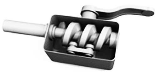
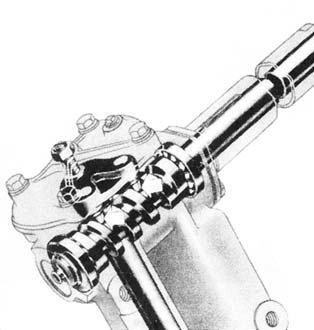
The Ross Gear and Tool Company started the manufacture of rear axles, universal joints, differential gears and steering gears in 1906, and in time the steering gear became the main product. Ross Gear and Tool Company was bought by TRW in the early 1960s and continued to build the Ross manual steering gear until 1971. The Ross cam and lever steering uses an input shaft with a worm cam at the bottom. This worm cam resembles a round bar stock with a spiral groove machined into the cam. A cam-lever is at the inner end of the cam-lever (Pitman) shaft. Studs (pins) on the lever engage the cam groove. At the outer end of the lever shaft, splines attach to the Pitman arm. The lever pins move with the steering wheel and cam rotation, swinging the lever shaft and Pitman arm clockwise or counterclockwise. One of the design features of this style is that it turns the Pitman shaft 90 degrees to horizontal so it exits through the side of the steering housing instead of the bottom. This allows a very compact design where necessary.

The Ross steering gear with single stud lever shaft and shim adjusted cam has been used by American Bantam, Crosley, and Graham models 74, 75, 80, 85, 90 and 95. The Ross twin-stud lever shaft is common to Jeep, IH Scouts and Studebaker vehicles. The problem with these designs is that, over time, the fixed studs develop a set of flats at opposite sides of each cone. A heavy duty version known as the Ross cam and roller type was developed and featured a single or twin stud mounted on double tapered bearings. The stud(s) is free to turn at point of contact with the lever. The single stud design was used in some of the ‘classier’ vehicles of the 1930s including Auburn, Duesenberg, Hupmobile, Pierce-Arrow, Reo Flying Cloud and Studebaker. It was also used by European manufacturers.

Minimal end play and free play at the steering wheel can be adjusted. First, check the frame for stress cracks around the mounting holes. Look for a tiny trail of rust. Discuss the repair with a frame shop. Check the bolts that hold the steering gear housing to the frame. They must be tight. If they are loose, remove them and check the shanks for wear. If the shanks are worn, replace the bolts with SAE grade 5 bolts (3 marks on head of bolt). Check lubricant and add SAE 140 weight gear oil, if the level is low. The fol-lowing adjustments can be made on these three types of Ross steering gear assemblies, if the steering gear is not excessively worn. If the steering gear cannot be adjusted, it must be removed for disassembly, inspection and rebuilding.
ADJUSTING CAM ENDPLAY
To adjust the Ross steering gear with shim-adjusted cam, disconnect the drag link from the Pitman arm. Loosen the adjusting screw in the side cover. This will free the stud in the cam groove and relieve the pressure on the worm cam bearings. Undo the column clamp. Remove the four bolts that hold the upper cover to the steering housing. Very carefully pry the upper cover into the column jacket about 1/4” to permit removal of the shims. Separate the top shims with a box knife. The 0.003” shims are on top and 0.010” and 0.030” shims are used in between the paper gaskets. Remove a shim or a number of shims, if necessary to remove steering wheel endplay. Reassemble the upper cover, and tighten the bolts. The steering wheel should turn freely without any drag. If this can not be accomplished by removing shims, the steering gear has to be removed for disassembly.
ADJUSTING LEVER SHAFT STUD BACKLASH

Endplay at the lever shaft will show up as backlash at the steering wheel. The groove in the cam is cut deeper in the ends of the cam than in the mid-position. This produces a high range through the mid-position and makes the groove narrower through this range. This allows an adjustment at mid-position of the cam where maximum wear occurs without causing a bind in the ends. Tighten the side cover adjusting screw until a very slight drag is felt through mid-position when turning the steering wheel slowly from one extreme to the other. It is important that the steering wheel does not bind at any point. A closer adjustment than just a very slight drag will NOT correct any steering condition, but it will damage and wear the parts. When proper adjustment has been made, tighten the lock nut, and give the steering wheel a final test. Make sure the drag link is properly adjusted and the Pitman arm nut is tight. If the steering wheel will not center after adjustment; the steering gear has to be removed for inspection and possible rebuild.
TWIN STUD LEVER STYLE CAM ENDPLAY
Disconnect the drag link. Loosen the steering housing side cover adjusting screw to free the studs in the cam groove. Loosen the column clamp. Remove the bolts holding the upper cover in place. Move the housing upper cover up about 1/4” to permit removal of shims. Remove as many shims as necessary to minimize the endplay of the worm cam and steering shaft. Reassemble the upper cover and column clamp. There should be very little drag so that the steering wheel can be turned and the endplay is removed. If this result is not obtained, the steering gear assembly has to be removed for disassembly and inspection.
CAM AND LEVER BACKLASH ADJUSTMENT
The groove in the cam is cut shallower in the straight ahead position of each stud. This produces a high range in the groove, which is equal at each stud, that causes closer mesh of the studs in the groove through the central position of travel of each stud. This feature permits a close adjustment for normal straight ahead driving and also permits take-up of backlash at this point after normal wear of the groove, without causing a bind elsewhere. Turn the steering wheel to straight ahead position so that each stud is at the high point of the cam. Never adjust with the studs at other points, as this will cause binding at the center position. Tighten the side cover adjustment screw until a very slight drag is felt through the central position when turning the steering wheel slowly from one extreme to the other. Do not adjust any further. The drag must be slight only be in the center position. Tighten the lock nut, and give the steering gear a final test. Make sure the Pitman arm is tight on the splined shaft and that the lockwasher and nut are tight also. Connect and adjust the drag link.
ROSS CAM AND ROLLER CAM ENDPLAY
Disconnect the drag link. If the column tube is held in the adjusting plug, loosen the column clamp bolt. If there is no clamp bolt, the tube is a tight press fit in the adjusting plug. Loosen the bracket at the dashboard so the tube will turn when the adjusting plug is turned. Loosen the steering housing side plate adjusting screw to free the stud in the cam groove. Back off the lock screw located at the top of the housing, and turn down the adjusting plug until there is no steering wheel endplay and little or no drag on the steering wheel. The steering wheel should turn freely with only the thumb and forefinger gripping the steering wheel rim. Tighten the lock screw and nut. Recheck steering wheel movement. Readjust, if necessary.
CAM AND LEVER BACKLASH ADJUSTMENT
This adjustment should always be made to the mid-position of the cam. Turn the steering wheel gently from one stop all the way to the other, counting the total number of turns. Then turn the wheel back exactly half way to center position. Loosen the side cover lock nut, and tighten the adjusting screw until a very slight drag is felt through the mid-position when turning the steering wheel slowly from one extreme to the other. It is important that the gear does not bind at any point. A closer adjustment will not correct any steering condition but will damage and wear the parts sooner. When the proper adjustment has been made, tighten the lock nut, and give the steering wheel a final test. Make sure the Pitman arm is tight on the Pitman shaft splines and the nut is torqued. Connect and adjust the drag link. Repair kits are available for drag links, if they can not be adjusted properly.
STUD ROLLER BEARING ADJUSTMENT
There is another adjustment on this steering, but it is located inside the housing. The two roller bearings that support the stud have to be adjusted for preload. This adjustment is usually done during assembly of the steering gear and does not require further adjustment.
ROAD TEST
Check tire pressure when the tires are cold before you do the road test. With proper adjustment of the steering gear there should be no more than 1/4” of freeplay at the steering wheel with the front wheels in straight ahead position. Freeplay in turn positions is not objectionable. If the vehicle wanders and it needs your constant attention to keep it in the lane during the road test, you have to troubleshoot for causes. With the vehicle parked on a level surface, engine off, stand outside the vehicle and reach through the driver's window and move the steering wheel back and forth. If the steering wheel moves more than an inch without the wheels moving, the most common problem is worn tie rod ends, worn idler arm or center link. Worn tie rod ends can also cause rapid tire wear. Correct these problems by replacing the necessary parts.
If the vehicle is pulling (drifting) to one side or the other instead of traveling straight and the front tire pressure is correct, check the tires first. It may be due to a tire bulge or a tire where the tread is starting to separate. Check for mis-matched tire tread, and check for tire size Tires have wear bars in the tread grooves to visually indicate wear. If the tread is worn down so the wear bars are flush with surrounding thread, the tire is worn out and needs to be replaced. Tend to this immediately. Then check the ride height. If it is not the same, check the springs. On coil springs if the top of the coil is shiny, the springs are weak and starting to bottom. On leaf springs check the arch. The flatter spring is the weak one. Check the spring shackle and control arm bushings for wear using a bar not a screwdriver. Metal bushings should have little or no play. Rubber or elastomer bushings will have a ‘bit’ of movement. If these parts check okay, the problem could be caused by a bent spindle. If the pull occurs only when the brakes are applied, the problem may be unequal braking. The vehicle will pull toward the side with the stronger braking effort. Uneven braking can be caused by a sticking floating caliper, stuck caliper or wheel cylinder piston, different grades of brake lining and contaminated linings caused by brake fluid or grease. Correct by repairing the brakes as required.
Check for uneven tire wear. The tires have to roll straight and true to minimize tire wear. If the wheels are out of alignment, tread wear will increase. Toe-in misalignment has the greatest effect on tread wear. Camber (tire perpendicular to road surface) misalignment causes wear on the inside or outside of the tread. If the tires are wearing unevenly, have the alignment checked.

REMOVING STEERING GEAR
When the steering gear can not be adjust-ed, it must be removed for disassembly and inspected for wear. A rebuild or replacement may be necessary. The following is a general procedure for the removal and rebuild of a Ross twin lever steering gear. The steering gear can be removed from the bottom or from the top. Refer to the service manual for your particular vehicle. This steering gear will be removed from the top with the column attached. Power wash the steering gear. Disconnect the battery. Move the front seat as far back as possible, and cover it with a seat cover. Remove the horn button/horn ring and steering wheel nut. Remove the steering wheel using a proper steering wheel puller. Do not pound on the steering shaft. It is hollow to permit the horn wire. Remove the steering column bearing spring. Check the clearance between the steering column bearing assembly and the steering shaft. If it is excessive, order a new bearing assembly. Disconnect the signal light wiring connector. Remove the bolts that hold the column to the dash or the dash brace. Remove the steering column dust shield located on the firewall. It is possible to remove this steering gear with the steering wheel attached. It's your choice.
Raise the front of the vehicle to a comfort-able working height, and set on safety stands. Remove the left front wheel. Remove the shifter linkages. Disconnect the horn wire if so equipped. The horn wire for the early military Jeep is located at the contact switch on the steering column. On other models it comes out the bottom of the steering housing. Remove the drag link. Remove the Pitman arm when the steering gear assembly is out of the vehicle. Remove the bolts holding the steering gear housing to the frame. Have a buddy inside the vehicle, and take the steering gear out through the firewall. Clamp the steering gear housing in a vise. Mark the position of the Pitman arm to the cam lever shaft before you remove it. Remove the Pitman arm using a proper puller. Do not try to pound it off. When the Pitman arm is removed check for a master spline which is wider than the others and locates the Pitman shaft in its correct position. Loosen the column clamp, and pull/twist the column off the steering gear housing. Examine the Pitman ball for wear, and if it is oval, replace the Pitman arm.
DISASSEMBLE STEERING GEAR
Loosen the cam lever shaft adjustment screw lock nut, and loosen the adjustment screw a few turns. Remove the side cover and gasket. Have a pan in place to catch any oil. Save the old gasket to use as a pattern, if necessary. Clean the exposed cam lever shaft with emery cloth. Remove the cam lever shaft. If it sticks in the bushing, the splined end may be bent. Remove the bolts that hold the housing cover, and slide the cover, shims and gaskets off the steering post. Spray penetrating oil around the upper cup, and let it soak in. Pull the worm cam assembly out of the housing. Remove the retaining rings. On some models the bearings (20) are loose and will fall out. On others the bearings are held in a cage. On some models ( Studebaker and Jeep/Willys ) there is a housing end cover and tube. The tube is for the horn wire and is easily bent. The tube keeps the oil out of the horn wire. On other models an expansion plug seals the end of the gear housing. If there were no oil leaks around the housing end ,cover leave it in place, and work around it. If there is leakage, remove the end cover, and if the tube is loose, braze it to the end plug.
Wash all the parts and inspect them for wear. Inspect the gear housing for cracks and any other damage. Make sure the oil hole at the base of the inner bushing support is not plugged. Check the adjuster screw for damage, and replace it, if it shows excessive wear. Inspect the bearings for pit-ting, chipping, rust and flat spots. Check the bear-ing races and cups for cracks and wear spots. The races are part of the worm cam, and if damaged or excessively worn, the cam and steering shaft must be replaced. Clean the cam threads on the worm with a wire brush, and check the threads for chip-ping and scoring. Usually the cam can be reused and bearing cups and bearings can be ordered. Clean the inside of the steering shaft by pushing a wad of steel wool through it a number of times.
Inspect the taper studs of the lever shaft for flat spots and chipping. The studs can be turned 90 degrees, and if you have access to a grinder, hydraulic press and an electric welder, it is not too difficult to do. Check the lever shaft for wear and fit of shaft in the bushings. The maxi-mum clearance for the bushings is 0.0025”. If the cam gear and lever shaft are suitable for reuse, order a rebuild kit from a reliable parts vendor. The cam gear lever shaft is available as a single purchase. Measure the length and diameter of the shaft, and order the proper one. Check this cost out first before you decide on machine shop service, if you do not have the necessary tools to modify the cam lever shaft. If, after inspection of parts, you feel they are all suitable for reassembly, order a lever shaft housing seal.
REASSEMBLE STEERING GEAR
Use a touch of sealer around the outside of the lever shaft housing seal. Install the seal flush with the housing. To hold the cam gear ball bearings in place during assembly, use wheel bearing grease. Grease the bearing race at the lower end of the cam gear, and place the first 10 bearings into the bearing cup. Press the cup against the bottom race. Install the retainer ring. Grease the top bearing race, and place the other 10 bearings in the bearing cup. Press the cup in place, and install the retainer ring. Slide the cam gear and steering shaft into the housing. Be careful to not bend the horn wire tube. Make sure the cups seat themselves and the steering shaft turns freely. Install the original shim pack and the upper housing cover. Use a thin coating of sealer on the gaskets and the shims to prevent any lubricant leakage. Cross-tighten the bolts. Try the steering shaft for end play. If there is end play, take a shim out. If the steering shaft turns tight, add a shim. Adjust for a very slight preload. Rotation should be smooth with no steering shaft endplay.
Tape the splines on the lever shaft, and apply wheel bearing grease to the shaft. Slide the lever shaft into the bushings and seal. Remove the tape.
Check for smooth operation by pressing against the lever and rotating the lever shaft. Make sure the lever goes as far as it can in each direction. Grease the adjuster screw contact point on the lever shaft. Apply sealer to both sides of the housing cover gasket. Install the housing cover, and apply sealer to the bolt threads. Coat the adjusting screw threads with sealer, and adjust the cam lever so there is a slight drag over center position without any binding. Tighten the adjuster lock nut, and test the steering to verify the slight amount of drag over the center position. Position the steering gear in a vise with a position similar to that of the vehicle. Remove the oil plug in the steering gear housing, and fill the housing with SAE 90-140W gear oil using a funnel and pouring slowly until lubricant is to the top of the hole. There is a lot of talk about using other types of lubricants in steering gears to supposedly stop leakage. A steering gear with minimal wear and solid gaskets/seal should not leak lubricant. Prime the bare metal, and paint it gloss black. Let it dry.
Replace the steering column bearing assembly, if the steering shaft was sloppy inside it. Use a three-fingered puller on a slide hammer to remove the old seal or drive it out from the bot-tom of the column. Drive the new one in from the top. Slide the column over the steering shaft and fasten with the clamp.
Install the steering gear assembly into the vehicle using the reverse order of removal.
HAPPY MOTORING.
Originally printed in Skinned Knuckles magazine, and copyrighted by SK Publishing/Skinned Knuckles Magazine. Reprinting of any portion prohibited without written permission of SK Publishing, PO Box 6983, Huntington Beach, CA 92615.
Subscriptions to Skinned Knuckles magazine is $28.00 for twelve monthly issues (within the U.S.). Contact Skinned Knuckles by mail at PO Box 6983, Huntington Beach, CA 92615; Website skinnedknuckles.net and click on Subscribe or PayPal. E-mail sk.publishing@yahoo.com, phone: 714-963-1558.


