Skunned Knuckles
Skunned Knuckles Articles
Steering and Independent Suspension Geometry – McQuay-Norris
(Caster, Camber, King-pin Inclination, Toe-in or out)
McQuay-Norris Manufacturing Co., The Mechanic’s Friend
An Automotive Engine and Chassis Textbook, Copyright 1955
The terms "Steering Geometry" and "Independent Suspension Geometry" are derived from the fact that front wheel alignment to produce good steering characteristics has to do with angles between key front end parts and the vertical, the same as mathematical geometry has to do with angles between lines on paper.
Front wheel alignment is the correct adjustment of steering angles.
The steering angles are caster, camber, king pin inclination, toe-in and toe-out as shown in Figure 5.

Caster: The angle that the king pin is inclined back from the vertical is the caster angle. In late model cars the manufacturer has provided machined bosses on the steering knuckle support forging. The caster angle can be accurately measured by placing a machinist's protractor containing a level gauge against these bosses.
On some cars the caster angle is adjusted by the upper plain or eccentric pin so that the top of the knuckle support moves forward or backward the necessary amount. On other cars uneven shimming where the upper control arms fasten to the frame will change the caster.
Camber: The angle that the front wheels are inclined outward from the vertical is the camber angle. This angle can be measured by placing a large carpenter's square on the level floor and against the tire of the front wheel which must be fully inflated.
The camber angle on General Motors cars is adjusted by turning the threaded eccentric pin which fastens the knuckle support to the shock absorber arm. On other cars this angle is increased by evenly shimming the upper control arm bracket away from the frame. Wheels with positive camber are farther apart at the top than at the bottom while wheels with negative camber are farther apart at the bottom than at the top.
King pin Inclination: The hole for the king pin in the knuckle support and for the king pin bushings in the knuckle or spindle are inclined inward at the top. Therefore, the angle which the king pin makes with the vertical is the king pin inclination.
When the camber can be adjusted to the specified angle it is unnecessary to check the king pin inclination.
Toe-in and Toe-out: If the front wheels are held by the tie rod or intermediate rods so that the front of the wheels are closer together than the rear, they are Toed-in. Likewise, if the front of the front wheels are farther apart than the rear they are Toed-out.
Toe-in or Toe-out can easily be measured by raising the front end, spinning each wheel and scribing a circumferential chalk mark on the inside wall of the tire. The car is then lowered with the wheels facing straight ahead. Next, the distance between the chalk circles on the two wheels is measured at hub level at the front and at hub level at the rear. The difference is the amount of toe-in or toe-out as the case may be. This is adjusted to specification by loosening and turning the sockets on the tie rods or intermediate rods.
When a repair shop plans to do considerable front end work it is advisable to purchase special-zed gauges for measuring the steering angles as they are more accurate besides being quicker and easier to use.
You have seen how necessary it is for all of the parts affecting steering to fit properly and be accurately adjusted. It can be "penny wise and pound foolish" to replace only one or two of the worn parts. For this reason more and more experi-enced shops are changing to the practice of installing all new replacement parts in the front end assembly when heavy wear is found.
REASONS FOR STEERING ANGLES
It is highly desirable to design the wheel sus-pension and steering so the car will travel straight ahead with a minimum of actual steering by the driver. This directional stability is dependent upon caster and king pin inclination more than any other factors. Camber has mostly to do with less road shock and easier steering when turning and parking.
1. EFFECT OF CASTER ON STEERING
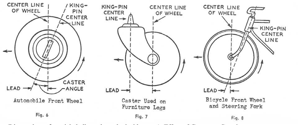
Ever since front wheels have been pivoted at the edge of the frame instead of in the center, wagon fashion, the pivots or king pins have been tilted back at the top so that a projection of the king pin will intersect the road a little ahead of where the tire contacts the road. (Figure 6). This causes the momentum of the car's chassis to actually lead the front wheels in a straight path, since any free mov-ing object tends to move in a straight line unless some force is exerted on it to change its direction. This is the same principle that causes a caster to line up and drag its wheel along in the direction a piece of furniture is moved. (Figure 7). It also explains, why a boy can ride a bicycle without his hands on the handle bars once the bicycle is moving along fast enough to have considerable momentum.(Figure 8).
A little caster is, therefore, desirable because it stabilizes steering in a straight direction. If excessive caster is used it will be noticeably hard to turn the car out of a straight path.
2. EFFECT OF CAMBER ON STEERING
In those early days when front wheels were first pivoted at the edge of the car's frame, the pivot or king pins operated in a vertical position and so did the wheels. It was soon discovered that the distance between the king pin and wheel vertical centerlines was causing the wheels to pull on rough roads and causing the bearing to bind. This distance was called the "scrub radius" (Fig. 9) and the undesirable effects on steering were reduced by making this turning radius as small as possible and developing wide tread, low pressure tires to cushion road shock.

However, the advent of four-wheel brakes caused serious front wheel pull, even with a small scrub radius. Therefore it became necessary to decrease the scrub radius to a minimum. This was accomplished by tilting the front wheel (Fig. 10) and inclining the king pin at an angle so that their center lines intersected close to the point where the center of the tire tread contacted the road (Fig. 11). Experience has shown that the tilt of the wheels, called camber, cannot be as great as the king pin inclination because too much wheel tilt causes excessive tread wear toward the outside of low pressure tires.

Late model passenger cars do not have much positive camber, if any, because the independently suspended wheels go up and down with-out changing camber appreciably. In fact, some cars are now designed with negative camber to counter-act the tendency for camber of the outside front wheel to increase when taking a corner or curve at average or higher speed. Therefore present practice is to have very little camber, but a 5 or 6° angle of king pin inclination.
Considerable camber is still needed on trucks because deflection of the front leaf springs and the axle under heavy loads reduces the positive camber.
3. EFFECT OF KING PIN INCLINATION ON STEERING
It is comparatively easy to understand that inclining the king pin (Fig. 11) so its centerline intersects the wheel centerline and the road at close to the center of the tire tread is a very satisfactory way to eliminate the scrub radius and its bad effects on steering. On the other hand, it may be a little more difficult to visualize and understand how this king pin inclination improves directional stability. The best way to get a clear understanding is to visualize or actually jack up a front end level. Then remove the hub cap of one wheel so you can look straight in at the spindle. You know that if the king pin was in a straight up and down vertical position the end of the spindle would just move in a horizontal plane when the wheel would turn. This could have no beneficial effect on steering. Now, switch your thinking to the actual case having the king pin tilted back from the vertical and turn the wheel from side to side. The tip of the spindle will describe an arc, the ends of which will be noticeably lower or closer to the floor than the center. This proves that an inclined king pin produces a small up and down movement between the spindle and the chassis when the wheel is turned.
In normal operation of the car the front wheels are against the ground which prevents the spindle from moving up and down as the steering wheel is turned. Consequently, the entire car is forced up when the front wheels are turned either to the right or left. Since this means that the weight of the car is raised slightly, releasing the steering wheel will allow the force of gravity to try to automatically straighten the wheels and stabilize the car. Only in the straight ahead position is the car weight the closest that gravity can get it to the ground. This stabilizing effect of king pin inclination keeps the car going generally straight unless the steering wheel is turned by the driver.
4. TOE-IN
Both caster and camber affect toe-in and therefore toe-in should be the last steering angle that is adjusted.
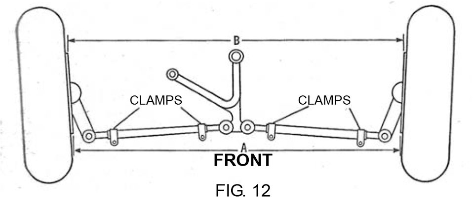
Positive camber (outward tilt of the front wheels at the top) gives the wheels a tendency to roll away from the car the same as a child's hoop will turn in the direction that it leans. To counteract this tendency, the front of the front wheels are toed-in. Therefore the amount of toe-in will be proportional to the amount of positive camber. In Figure 12 toe-in is the fraction of an inch that B is longer than A.
As we have seen when discussing camber, independently suspended wheels do not need much camber, and so many present day cars are designed with zero camber or negative camber. As a result some of the toe-in specifications are very small.
5. TOE-OUT ON TURNS
It is easily understandable that when a car is steered around a turn, both front wheels turn around the same center but the outside wheel has a larger "turning radius" by the width of the car. In order to avoid tire wear from scrubbing against the road surface, both wheels must be directed by their steering arms, so the wheels remain perpendicular to their turning radius as they roll around the turn.
This is accomplished by so designing the relationship between the steering arms and king pins that the outside wheel is steered at a smaller angle to the car frame than the inside wheel. The difference between these angles is called the "toe-out on turns."
The toe-out is always checked by turning the outside wheel to exactly a 20° angle with respect to the centerline of the car or frame and then measuring the angle the inside wheel makes with the centerline. See Figure 13. The inside angle should be greater than 20° by the specified "toe-out on turns".
If not the same, one or both steering arms are bent. Each arm should be compared with a new one to determine whether one or both are damaged and need replacement. In most cars, lines extended rear-ward through the king pin and steering arm attaching hole on each side will intersect in the center of the rear axle, when the proper relationship exists.

SERVICING THE FRONT END ON 1940 THROUGH 1954 CARS
Most cars today use the short and long arm type (SLA) independent front suspension consisting of upper and lower control arms, shock absorbers, knuckle support and coil spring. Ford, Mercury and Lincoln cars used a conventional axle and trans-verse leaf spring until 1949.
1. HOW CASTER, CAMBER AND TOE-IN ARE ADJUSTED
Caster and camber are adjusted by loosening the lock bolt in the top of the knuckle support which clamps the threaded eccentric in the center of the upper outer pivot pin. Turning the threaded pin or bushing changes caster and also camber. When the adjustment has been made to the specifications in the following table, tighten the lock bolt.
In some cases after caster has been correctly set it is necessary to cold bend the knuckle sup-port forging in order to get the specified camber angle. This should be done by a specialist who has the necessary equipment. Never heat any wheel suspension part so it will bend easier, as this will ruin the heat treatment and make the part unfit for further use.
On Henry J cars caster is adjusted by shims placed at the inner pivot shaft. A shim at the rear bolt increases caster while a shim at the front bolt reduces caster angle.
On Studebaker cars special shims are used behind the upper suspension arm bracket where it fastens to the frame. Uneven shimming changes caster. Even shimming changes camber.
Toe-in is adjusted by loosening the clamps on the intermediate rods and turning the sleeves or rods. To decrease toe-in, turn both the left rod and the right rod in the direction that pulls the back of the wheels in toward the center a like amount to get the specified toe-in setting. Vice-versa to increase toe-in.
2. HOW TO REPLACE COIL SPRINGS
Raise the front end of the car about 8" by jacking up the center of the front crossmember. Place safety jacks under the side frame members so the roller jack can be used as follows:
Place the roller jack under the lower inner threaded shaft and raise just enough to firmly con-tact the shaft. Disconnect the stabilizer link. In cars using the telescoping type of shock absorber located inside the coil spring, it is of course necessary to disconnect the shock absorber before removing the coil spring.
Then remove the bolts which attach the lower inner shaft to the frame crossmember. Slowly lower the jack until the A frame releases the coil spring so it can be lifted out.
Slip in the new coil spring and be sure the ends fit properly into the spring seats and that any silencer or shim is in its proper place. Raise the jack so the shaft goes back into position and use a drift pin to line up the bolt holes. Install and tighten the bolts attaching the lower inner shaft to the frame crossmember.
In cases where it is desired to replace a threaded joint as well as the coil spring, the wheel suspension should be disconnected at the joint and the coil spring replaced at the same time. However, be sure to first support the weight of the car by means of safety jacks under the sides of the frame and have a roller type jack under the lower support arms (A frame) before loosening the joint.
3. HOW TO REPLACE OUTER PINS AND BUSHINGS
Place a jack under the lower control arm assembly and raise car so wheel can be removed. Then the upper and lower outer pins and bushings can be disassembled.
The new bushing for the lower end of the knuckle support should be screwed in and tightened. Then screw the threaded pin into the control arm through the bushing and tight into the rear control arm, seeing that the knuckle support, not the bushing, is centered between the control arms.
The upper eccentric threaded pin has left hand threads and two starting threads. When screwed through the knuckle support and upper arms and when the eccentric is facing out, the eccentric should be centered in the knuckle support forging. If not, unscrew eccentric pin and start over on other starting thread so it will center when in operating position and eccentric is facing out. Be sure that the new dust seals are installed at the location of the old ones.
4. HOW TO REPLACE KING BOLTS AND BUSHINGS
Jack up front end at center of frame cross member. Remove wheel and wheel bearings. There is no need to disturb hydraulic brakes, except on Chrysler cars. Just detach backing plate so it can be slipped off spindle or knuckle and fastened to frame out of the way on a wire hook.
Drive lock pin out. Remove welsh plug and drive king boIt down, forcing out lower welsh plug. Hold knuckle as king bolt falls out. In the case of Ford models before 1949, the mushroom head on the king bolt makes it necessary to drive it up to remove. A special pin removing press is a very useful tool, as king bolts can be rusted very tight.
The old bushings are then pressed out of the knuckle forging and new ones from a replacement parts kit are pressed in with grease holes lined up. They are reamed or honed to fit the new king bolt. Always remove the grease fittings so a drill can be run into the bushing to be sure the holes are open into bushings, and so all dirt and cuttings can be washed out before assembling.
Hold the knuckle in operating position and drive the new king bolt into place from the top, with the thrust bearing properly located. Shims may be furnished and if so the required number should be installed to eliminate up and down play.
Drive in the lock pin securely and install the new welsh plugs. Pack the wheel bearings with proper grease and adjust the spindle nut. Replace wheel and remove jacks.
Due to Hudson cars having the thrust bearing on top of the king bolt, the steering arm must be removed by unscrewing the nut and driving out the steering arm with its woodruff key. Then take out grease fitting so a small driver can be put in the grease hole to drive the king pin down and out.
Both the removal of the king pin and the installation of the 7 loose ball bearings are usually so difficult that time and aggravation can be saved by removing the knuckle and knuckle support from the car as a unit. Then the knuckle can be held in a vise and the hardened steel top bushing cut off with a torch so a large driver can be used to drive out the king pin.
After the new hardened steel bushings requiring no reaming are installed, place the new grease seal between the flange of the upper bushing and the knuckle. Be very careful to start the king bolt from the bottom so that the key slots will line up. After pressing the king bolt into place, the seven ball bearings can be dropped in through the grease hole in the upper bushing and pushed into the race by means of a wire. Then complete the assembly.

As a general rule, tightness is desired where the bushings or pin screw into a forging, but a little clearance or room for grease must exist between the inside of the bushings and the pins and shafts. The threads of a new pin or shaft fit down snug in the threads of the new bushings so there will be no side movement (see Fig. 14) when the weight of the car is on the wheels.
However, front end specialists prefer a minimum of grease clearance so they can get the most accurate adjustment of the steering angles, thereby giving the car owner the smoothest possible ride. Therefore, McQuay-Norris threaded wheel suspension parts, while being of the original design, metallurgy and heat treatment for maximum safety, are made with the special close thread fit preferred by front end specialists throughout the country.
In order to arrive at a general figure for use in discussing this subject, we have averaged the various thread clearances which are the specifications of different car manufacturers for the working parts of their independent front wheel suspension. The following are a few examples:
0.011 to 0.020
0.008 to 0.017
0.012 to 0.021
0.017 to 0.026
0.017 to 0.028
0.017 to 0.038
The overall average clearance between threads is 0.016. About this much is considered necessary by the car manufacturers so that front end assembly on their mass production lines will go along smoothly.
After a new car of any make has run a few thousand miles over all kind of roads, the frame members and the major suspension parts probably will have been jolted into somewhat better alignment than when originally assembled. Therefore, by the "time the steering angles need adjustment, the above conditions plus wear on the threads of the shafts, pins and bushings are causing too much play to permit holding the adjustments when the car is in operation. At that time not only are new threaded parts needed, but they should be special McQuay-Norris replacement parts with respect to thread clearance.
Our survey of outstanding alignment shops showed that the preferred thread clearance among these specialists was about half of the overall 0.016 clearance for new car parts and so all McQuay-Norris parts of this type are made with an average clearance of 0.007 or 0.008. This clearance permits thorough lubrication of all threads and does not pro-duce any binding or tightness that might cause stiff operation or seizure.
It requires rigid control of production tolerances to insure the desired thread fit because a tight binding fit is just as desirable as a loose fit to the specialist who wants to be proud of the work he turns out.
HOW TO CHECK BENT SPINDLES
Erratic steering, wander and tire wear can be caused by a bent spindle, even if caster, camber and toe-in are correct.
To check for a bent spindle on a front wheel alignment gauge, first check camber and king-pin inclination. Add these two values together for each side of the vehicle and compare totals. If the total for both sides is exactly the same, it may be assumed that both spindles are in good condition, because it is unlikely that both would be bent exactly the same amount.
Ordinarily it may be assumed that the bent spindle is the one having the greater total of the two, because in most cases spindles bend downwards.
If a spindle is removed for replacement of king bolt and bushings, it can be checked for alignment by clamping a dial indicator mounting on the outer bearing surface and adjusting the indicator tip against the inner bearing surface. When clamp is rotated, indicator should not run out more than 0.002” if spindle is not bent.
BRIEF NOTES ON ALIGNMENT EQUIPMENT
Many alignment gages include a spirit level-like a carpenter's level-plus a protractor for measuring degrees.
For convenience in turning the wheels as required for some of the. testing, turntables are in general use.
Gages furnished for front wheel alignment may clamp into position, be bolted to the wheel, held with a spring and chain, or secured with mag-nets. Whatever the variation in design, the basic essential is accuracy and ease of handling.
Most aligning equipment checks caster angle by measuring the camber angle at two positions of the wheel. The difference between these readings gives the caster angle. Most equipment today is calibrated to make these readings when the road wheel is turned 20 degrees from the straight- ahead position in one direction and then swung 20 degrees from the straight-ahead position in the other direction.
Toe-in figures, as given in specification tables, are generally used with adjustable or telescoping gages. These either contact the rim, the side of the tire, or measure a scribed mark in the center of the tread.
Toe-in adjustments are simple. The steering wheel is turned to its center position, the clamps on the tie rods loosened, and the rods turned until the toe-in gage shows the correct value. Then the clamps are re-tightened.
Toe-out on turns is checked after setting the toe-in. Toe-out is measured with the aid of turntables. These turntables have their edges marked in degrees.
The degree of toe-out is engineered into the vehicle. It is the result of the angle at which the steering knuckle arms are positioned inward from a straight fore-and-aft line.
Improper toe-out requires replacement or straightening of the steering arms.
After any adjustment, a recheck of settings is always desirable; but in the case of a change in caster or camber, it is most important to see that changing one has not upset the other.
The ball joint type of independent front wheel suspension now being used on all cars produced by the Ford Motor Company is designed to give positive control of wheel movement under all operating conditions and to prevent tire wear and squeal.
The two ball joints fasten the ends of the spindle forging to the outer ends of the short and long control arms. A coil spring is used in the customary position between the control arms. The inner ends of the upper control arms contain mold-ed rubber bushings, which turn or flex on a shaft that is fastened to the car's frame.
The principal difference between the Ford design and the Mercury-Lincoln design is that on the Fords the side of the upper inner shaft that is facing toward the engine is fastened to the shock absorber bracket, while on the Mercurys and Lincolns the wheel side of this shaft is against the bracket. Therefore, removing or adding shims between these upper inner shafts and the bracket to adjust caster and camber will have just the opposite effect on Fords that it does on Mercurys and Lincolns.
The lower control arms also contain rubber bushings but are individually mounted to the cross frame member by means of large plain bolts.
The universal type movement of the ball joints, which can be compared to the hip or shoulder joints in the human body, combines turning or steering movement with up and down wheel movement, thereby eliminating king bolts and bushings. However, ball joints are very special heavy duty sockets which have not been used long enough for wheel suspension to be free of design problems and so should be a very good maintenance item. Therefore, it is time for repairmen to get acquaint-ed with servicing this newest type of front end. Following is a brief procedure on replacing Ford ball joints.
Disassembling a ball joint front end is not a great deal different than disassembling the threaded joint type of front end which is used on all other makes of cars. After raising one wheel and placing a safety jack under the frame just back of the rear control arm, the wheel hub and wheel bearings are removed. Then the brake carrier plate is unbolted and tied out of the way. Now a jack is placed under the lower control arm assembly to let the coil spring down slowly when the lower ball joint is unfastened.
First, remove the shock absorber and disconnect the stabilizer from the lower arm. Then loosen the upper and lower ball joint stud nuts about two turns, but do not remove nuts. To prevent damage to the stud threads from hammering, a special remover tool made like a turn buckle and fitted between the two studs should be used to break the studs loose from the tapered seats in the spindle forging.
Next, remove stud nuts and lower the jack slowly until all tension is off of the coil spring. Then the ball joints can be unbolted from control arms and taken over to a bench vise for inspection and checking.
To check, attach a spring scale to the cotter pin hole in the stud. If the pull required to move the stud of the lower ball joint is less than 8 lbs., it must be replaced. Check the upper ball joint by putting the nut on the stud and turning the stud with a torque wrench. If turning effort is not within 25 to 40 inch lbs. torque, install a new upper ball joint.

Ball joints that pass the above check can be reused, but should not be washed out with a solvent, because it is very difficult to regrease them properly.
In reassembling the front end, tighten the nuts on the bolts that fasten to the ball joints and control arms to a 65-90 foot lbs. torque for the lower socket and 28-45 foot lbs. for the upper socket. Tighten the rubber bumper nuts to 20-35 foot lbs.
The nut on the stud of the ball joints should be tightened to 100 foot lbs. torque for the lower socket and 80 foot lbs. for the upper socket.
When the brake carrier plate is assembled to the spindle forging, tighten the upper nuts to 28-43 foot lbs. torque and the lower nuts to 70 foot lbs.
The following factory duplicate ball joints are furnished by McQuay-Norris:

Chevrolet Type
The 1955 Chevrolet cars are equipped with ball joints of their own design and manufacture. More will be known about them after they have been in service for a few months and then replacement parts will be available.
Originally printed in Skinned Knuckles magazine, and copyrighted by SK Publishing/Skinned Knuckles Magazine. Reprinting of any portion prohibited without written permission of SK Publishing, PO Box 6983, Huntington Beach, CA 92615.
Subscriptions to Skinned Knuckles magazine is $28.00 for twelve monthly issues (within the U.S.). Contact Skinned Knuckles by mail at PO Box 6983, Huntington Beach, CA 92615; Website skinnedknuckles.net and click on Subscribe or PayPal. E-mail sk.publishing@yahoo.com, phone: 714-963-1558.


