Skunned Knuckles
Skunned Knuckles Articles
by Orest Lazarowich
Steering Linkage Part 2
Most North American vehicles built with independent front suspension (IFS) before the mid 1950s used kingpins to support the steering knuckle. After that time the steering knuckle and the steering knuckle support combined into one unit called the spindle support and was sup-ported by ball joints. The kingpin was eliminated. In both systems two control arms or A-frames (wishbones) upper and lower locate the wheel. The control arms allow the wheels to move up and down and prevent forward and rearward movement. The control arms on kingpin suspension are parallel to their pivot points. Each control arm has two mounting points to the chassis and one at the steering knuckle. On vehicles using kingpins the inner control arm bushings are screwed into the control arms and pivot on a shaft. The top of the outer control arm is fastened to the steering knuckle support by an eccentric pin and threaded bushing to allow for camber adjustment. The bottom of the lower control arm is supported by a threaded bushing and pivot pin so caster can be adjusted. The steering knuckle is held to the steering knuckle support by the kingpin. Normal wear and/or lack of lubrication will cause the tie rod ends and the steering link-age to loosen up. The problem is that you get used to the play in the steering wheel and compensate for the loose steering. Greasing worn joints will not stop the vehicle from wandering when you are driving straight.

Independent front suspension in America did not change much until 1978 when the com-pact rear drive Ford Fairmont and the Mercury Zephyr adopted the MacPherson strut suspension which is named after its inventor. It consists of a strut combined with a spring and a shock absorber that connects the wheel to the frame of the vehicle. The strut is cheaper and lighter than the double A-frame design. It bolts directly to the body structure on top and the wheel and control arm with a ball joint at the bottom eliminating the upper control arm. The steering linkage was changed to rack and pinion which also eliminated the steering gear box and other steering linkage rods. Strut suspension came into common use in the 1980s along with front-wheel drive and rack and pinion steering.
There are many points of wear on the kingpin style of front suspension. Inspect the tires for under inflation which can cause road wander and poor recovery. Unbalanced tires and/or worn inner bushings on the control arms can cause vehicle shimmy. Abnormal wear such as front tire cupping can be caused by misalignment of the front tires and worn coil springs/shocks which will also cause the vehicle to sway and become unstable. A little bit of wear at the kingpins, control arms, tie rod ends, sway bar and steering linkage adds up to a lot of wear and the result is road wander. You may have to replace kingpins and bushings, tie rod ends and linkage and the inner control arm metal bushings and pivot shafts on both control arms. This can be very costly to repair so troubleshoot every part of the steering linkage very carefully for excessive wear. Measure the vehicle ride height to check weak or sagging coil springs. Use a push/pull tape and measure from the ground through the center line of the wheel to the front fender lip. With a difference of more than an inch check the lower control arms for damage and the springs for bottoming out.
The shock absorbers provide resistance to the movement of the spring. They also keep the tires in contact with the road surface. If the shock absorbers are worn, the vehicle bounces down the road until all the spring energy is used up. Do a ‘bounce test’ on the shock absorbers. Push down on one corner of the vehicle, and let go. The vehicle should bounce up and level out. If it continues to bounce more than a couple of times, the shocks are weak and should be re-placed. The most common type of shock absorber is the telescopic hydraulic shock absorber. If these shocks are dented, bent or leaking oil, they must be replaced in pairs. If your vehicle uses the rotary single or double lever shock absorbers and they show signs of leaking, they should be rebuilt/exchanged. If the shafts are worn, they must be reground and bushings and seals installed by a rebuild shop. If there is no sign of oil leakage, check the oil level. Top up with hydraulic jack oil applied by a squirt bottle.
Support the vehicle on safety stands under the control arms to compress the coil springs. With the vehicle in gear and rear wheels blocked, wear safety glasses, and grab a tire at the top and bottom and try to rock it in and out. Move your body around and look at the kingpin location to see if there is any movement. If there is noticeable play at the kingpin check the other wheel. If tire movement is similar at this kingpin, the kingpins and bushings need to be replaced on both sides. Do not mistake wheel bearing wear or adjustment for kingpin wear. Check the outer tie rod ends for wear. Place your hands at the 3 and 9 o'clock positions on the tire and move the wheel back and forth. If there is any play in the wheel, the tie rod ends may need replacing. Remove the front wheels, and recheck for wear at the king-pins and tie rod ends. Steering knuckle supports can be of two types. One is similar to a straight axle where the steering knuckle slides over the steering knuckle support and the kingpin bushings are located in the steering knuckle (GM). In the other style the steering knuckle fits into the steering knuckle support and the kingpin bushings are located in the steering knuckle support (Ford/Mercury).
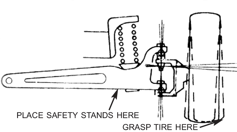

Check the coil springs for stress cracks and broken coils. Shiny spots be-tween the coils indicate the springs are bottoming out. Use a piece of 2x4 lumber about 4 feet long against the brake drum, and pry up to check for excessive movement at the top and bottom of the steering knuckle support. Wear at these two pivot points will change the caster and camber settings. You can check the upper control arm inner bushings and shaft for wear by prying against the control arm with a bar. With the coil springs compressed the inner lower control arm bushings are difficult to check for wear. Slide under the vehicle and check the idler arm and the center link tie rod connections. Move the parts up and down to check for excessive movement of parts. The idler arm adds stability to the center link and tie rod assembly. As it wears the freeplay in the steering wheel increases. If the ball joints on the center link are worn the entire center link must be replaced. Before you start work make sure you can purchase good quality parts. Plan your work procedures.
KINGPIN REPLACEMENT
This procedure is for a vehicle which has the kingpin bushings located in the steering knuckle support. Safety stands can remain under the lower control arms. Wear safety glasses. Back off the brake shoe adjuster to move the brake shoes away from the drum. Remove the spindle dust cover, cotter pin and castle nut. Draw the brake drum toward you, and pull off the drum. Catch the outer bearing, and keep it with the drum. Remove the four bolts that hold the brake backing plate to the steering knuckle. The bottom two bolts hold the steering support arm which comes off with the tie rod end. Sup-port the backing plate and brake shoes to prevent strain on the brake flex hose. The steering knuckle is now fully exposed. Check for excessive wear at the inner upper and lower control arms. Check for wear at the upper and lower steering knuckle support. If worn parts need re-placing, make sure you can purchase them be-fore you take anything apart. To remove the worn kingpins first remove the upper and lower dust caps. New ones come with the kingpin/bushing kit. These caps are actually Welch plugs which are an American invention.
Remove the tapered pin that holds the kingpin in place. Note the location of the thrust bearing. Drive out the kingpin using a punch and a hammer. Remove the grease fittings (zerks). This is another American invention by inventor Oscar Ulysses Zerk. Use a bearing/seal driver of the correct size to drive out the old bushings. You can also use a socket of the correct size. Clean the grease fitting hole with an air blast to remove any old grease. Clean up the bushing surfaces with emery cloth. Install the new bushings using a bushing driver or a socket. Line up the hole in the bushing with the grease fitting hole. Make sure the bushing goes in squarely. Pressing the bushing in compresses them and it should be reamed to size, if you have the use of a reamer and a pilot busing, ream the bushings.

Use plenty of cutting oil and turn the reamer slowly in a clockwise direction. If you do not have a reamer, use a brake hone and check the fit frequently. The kingpin should push into the bushings and not slide through them. Clean the inside of the bushings with brake spray and an air hose. Scrape fresh grease into the thrust bearing. Clean the hole in the steering knuckle with emery cloth, and install it into the steering knuckle support with the thrust bearing in place.

Check the steering knuckle for up and down movement. Use shims to take up any slack between the steering knuckle and the steering knuckle support. There should not be any up and down movement of the steering knuckle. Grease the bushings, and slide the kingpin into the top of the steering knuckle support with the flat side aligned with the hole for the tapered pin. Drive the kingpin in until it lines up with the hole for the tapered pin. Install the tapered pin, and drive it in place. Install the lockwasher and nut and tighten. Install the new dust caps, and hit the rounded surface with a ball peen hammer to spread the cap. Install the grease fittings, and pump some grease into them. Move the steering knuckle back and forth to make sure it has smooth movement. Install the backing plate and the steering knuckle support arm. Replace the tie rod end, if it is worn. Service the wheel bearings, if the grease is old and not the consistency of peanut butter. Install the brake drum, and adjust the wheel bearing. Use a new cotter key. Install the dust cap. Install the wheels and hub caps. Check the tire pressure. Lower the vehicle, and road test. Steering should be straight and not wander. If the vehicle does wander and is hard to control, search out a shop that has the experience with vehicles that use eccentric and threaded bushings for camber and caster adjustments, and have the wheel alignment checked.
BALL JOINT REPLACEMENT
Ball joints are spherical bearings that connect the control arms to the spindle support. The control arms allow the wheels to move up and down and are attached to the frame with bushings. The bushings consist of an outer metal sleeve, a rubber or polyurethane bushing and an inner metal sleeve. During the road test if the steering wanders left to right and you hear a clunking noise coming from the front suspension, suspect the ball joints. Inside tire wear is also a sign of worn ball joints. To check for ball joint wear when the coil spring is placed be-tween the lower suspension arm and the frame or torsion bar suspension is used, place the safety stands under the suspension arms, and raise the front tires off the ground. To check the bottom ball joint which wears out most often use a piece of 2x4 lumber about 4 feet long and lever the tire up, and then let it down. If you hear a clunk when it is let down, the bottom ball joint is loose. This is excessive play, and the ball joint must be replaced. Rock the tire, and listen to any sound coming from the upper ball joint. If it is worn it must also be re-placed. Remove the wheels, and visually inspect both upper and lower ball joints. Look for torn dust boots or grease around the ball joints which allow dirt and water into the ball joint. Some ball joints have grease fittings that double as wear indicators. When the grease fittings have receded into the housing the ball joints need to be replaced. Use a pry bar against the upper and lower control arms to check for wear at the inner control arm bushings. If movement is excessive, change the bushings. Rubber bushings that are dried out or rotate in the metal sleeve can cause squeaks and have to be replaced. Silicone spray is a temporary solution. If control arm wear is minimal, remove/replace the ball joints. Check the tie rod ends, center link and idler arm for excessive wear and replace as necessary. This is the time to replace the coil springs, if they are weak and starting to sag. Troubleshoot both sides. Order the necessary parts.
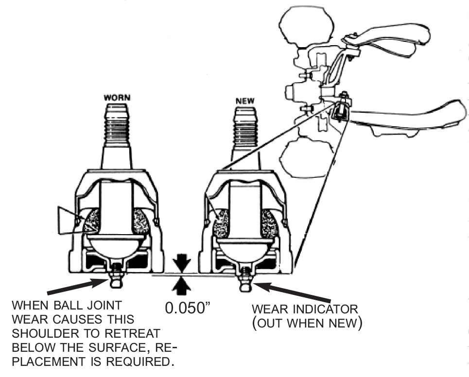
Move the safety stands under the frame behind the front wheels to provide working room. Wear your safety glasses. Block the rear wheels. Some ball joints are screwed in place while others may be riveted, pressed, bolted or spot welded. Refer to the service manual. The following procedure will cover ball joints that were riveted and have been replaced using nuts and bolts. Disconnect the shock absorbers. Dis-connect the sway bar. It may be connected to the control arm with a link bolt. Loop a safety chain around the coil spring and the hole in the lower control arm to keep the coil spring from flying out when the lower ball joint is disconnected. A flying spring will hurt. If you are replacing the coil springs, cut them in half with a torch and work safely.
Vehicles of the late 1950s and early 1960s were still using drum brakes at the front. Disc brakes were optional. To replace ball joints on these early vehicles leave the brake drums on unless you are planning brake work. Work on the bottom control arm and ball joint first. Slide a floor jack under the lower control arm of the ball joint being re-placed.
Remove the cotter pin and the bot-tom ball joint nut. The cotter pin is an-other American invention. If you do not have the use of a pickle fork, hit the joint area where the ball joint stud goes through with a heavy hammer backing it up with another hammer. The blow distorts the hole in the spindle support and loosens the stud. Use this same method to loosen the tie rod ends, if they need replacing. Lower the bottom control arm until it is clear of the ball joint. The safety chain will keep the coil spring in place. Pull the brake drum assembly forward, and tie it out of the way. It may be necessary to remove the tie rod end on some vehicles. If the control arm does not move up and down easily, the cross shaft may be seized to the inner bushing. To remove the lower control arm pull the spring out of the frame. Re-move the lower control arm, and bring it up to the bench. If the control arm is bent, it must be replaced. Clean off any mud or grease that is on the ball joint. Spray the nuts and bolts with penetrating oil. Remove the nuts and bolts and the old ball joint. On older vehicles you have to re-move one of the bushings first, and then remove the control arm cross shaft and the other bushing. There are a number of ways to remove the shaft and the bushings depending on what tools you have.
If you have the use of a hydraulic press, you can use the shaft as a driver to press the bushings out. To prevent compressing the control arm use a spacer made out of a piece of pipe that will fit between the inside of the control arm bushing locations or use a small bottle jack. Re-move the nut and washer on one end. Support the control arm of a piece of pipe larger than the outside diameter of the bushing. Press on the cross shaft until the opposite bushing is pressed out. Use plenty of penetrating oil. Reverse the procedure, and press the other bushing out. On some models the bushing extends into the inside of the control arm. Use a drill with a ¼ inch bit, and drill out the rubber bushings. Take a punch, and collapse the outer metal sleeve portion of the bushing. Use plenty of penetrating oil on the part of the bushing in the control arm, and drive the bushing out. Remove the shaft, and then drive out the other bushing. If you are lucky and the inner sleeve of the bushing comes out with the bushing itself, do a victory dance. Examine the cross shaft to see if it can be reused. If it is corroded, the shaft has to be replaced. If the inner sleeve is corroded on the shaft, do not spend time removing the sleeve. Replace the cross shaft. Your life might depend on it.
Clean the control arm. Follow the procedure in the service manual for replacing the cross shaft and bushings. Install the ball joint bolts with the nuts facing up. Torque to specifications. Install the new grease zerk. Paint the rebuilt as-sembly with black paint, and install it on the frame. Push it down to its lowest point, and place the jack under it. Install the new/original spring with the necessary insulators, if used. Slide the spring in place with the tight coils facing up and into an upper crown in the frame. Raise the lower control with the jack to get some pressure on the spring. Use a bar, and slide the bottom of the springs into the dish in the control arm. Fasten the safety chain. Raise the control arm and fit the ball joint stud into the spindle support. In-stall the castle nut and torque to specifications. Install the cotter pin. If the hole does not line up, tighten the nut. DO NOT loosen it. Slide the co-ter pin in, and bend the longer side down over the nut and stud. Bend the shorter side up over the nut, and use diagonal side cutters to cut off any extra length. Replace the jack with a safety stand. Hydraulic jacks can and do leak. You want the lower control arm to stay positioned and not move down.
Remove the upper ball joint nut, and pull the steering spindle off the ball joint stud. Tie the brake assembly to the frame to prevent strain on the brake hose. Check for wear at the the upper control arm bushings by moving the control arm side to side and up and down. If up and down movement is limited, remove the control arm and replace the bushings. When you disconnect the upper control arm there should be alignment shims on the bolts. Remove and identify their lo-cations on either the front or back bolts so they can be replaced in their original locations which is probably the original camber and caster alignment settings. Clean the upper control, and re-move the ball joint. Replace the bushings and cross shaft, if it is worn. Paint the assembly black, and install. Connect the ball joint stud to the spindle support. Torque the nut to specifications, and install the cotter pin and set it. Replace any of the steering linkage parts that are worn. When replacing tie rod ends count the number of turns it takes to remove the tie rod, and screw the new tie rod in the same distance to maintain the toe-in adjustment. Remove the safety stand, and install the shock absorber. Service the other side. Install the sway bar.
Load the grease gun with a good quality multi purpose chassis grease that can be used on tie-rod ends, ball joints and control arm shafts. If you are servicing the wheel bearings that run at high speed and temperatures, you must use a formulated wheel bearing grease. Do not use a multi purpose chassis grease on wheel bearings. Start with the ball joints, and grease the ball joints until the boot starts to swell. Do not over grease and damage the seal. To lubricate a sealed ball joint use a grease zerk needle adapter attached to a regular grease gun. Insert the needle into the side of the boot where the boot and ball joint meet. Pump in grease until the boot swells. Wipe the grease fittings clean on the steering linkage. Grease the tie rod ends, and wipe away any excess grease. Slide under the vehicle, and grease the center link and idler arm. Install the wheels, and lower the vehicle. Check tire air pressure. Locate an alignment shop and have the camber, caster and toe-in checked/adjusted. Road test.
HAPPY MOTORING.
Originally printed in Skinned Knuckles magazine, and copyrighted by SK Publishing/Skinned Knuckles Magazine. Reprinting of any portion prohibited without written permission of SK Publishing, PO Box 6983, Huntington Beach, CA 92615.
Subscriptions to Skinned Knuckles magazine is $28.00 for twelve monthly issues (within the U.S.). Contact Skinned Knuckles by mail at PO Box 6983, Huntington Beach, CA 92615; Website skinnedknuckles.net and click on Subscribe or PayPal. E-mail sk.publishing@yahoo.com, phone: 714-963-1558.


